Winged keels, Deed of Gift-controlled matches, rule changes, cheating allegations. The America’s Cup is no stranger to controversy, and for much of the past decade, the hot button has also been the new big thing: foiling. To traditionalists, this is heresy. The Cup is a yacht race, and sailing boats belong in the water. Others believe the Cup is a design, engineering and innovation contest that should be raced at the bleeding edge of technology. So is the modern AC75 the spiritual descendant of the 1903 superboat Reliance? Or should it go the way of the Seawanhaka Rule—collateral damage to Reliance’s one-sided victory? It may yet come to pass. No one knows what the 37th edition of the Cup will look like at this point, but whatever the future, the genie has soared out of the bottle: Foiling is now at the forefront of sailing.
It’s been one of those overnight successes that took a long while to come about: Italian Enrico Forlanini achieved 42.5 mph with a small, one-person foiling powerboat just three years after Reliance’s win. The science is well-understood, at least in macro terms; hydrofoils use the same physics as sails and aircraft wings. They guide the flow of water around them, generating low pressure on one side and high pressure on the other. The resulting imbalance creates enough lifting force to get the boats up in the air, and that’s a lot quicker because the hull doesn’t have to push water out of the way anymore.
The original foiling Cup boat was the AC72 in the 34th America’s Cup in San Francisco. It was a Team New Zealand innovation, and they achieved it despite a class rule that was otherwise written to keep the boats in the water. The central innovation in 2012 was to shape the daggerboard into a foil that could provide both lift and leeway resistance. The next part of the challenge was to control the lift sufficiently well to enable stable flight. The rules controlling the AC72 forbid any part of the foil to move independently, so the New Zealanders couldn’t use flaps—an adjustable trailing edge that controls the amount of lift from aircraft wings. Instead, they moved the whole foil to change its angle of attack to the water. This has the same effect, varying the amount of lift generated. The AC50 that raced in the 35th Cup in Bermuda also forbid movable parts on the foils. In contrast, the AC75 is a new development because it specifically allows flaps on the two T-shaped foils, ushering in a new era in foiling Cup boats.
If we want to understand the challenges and opportunities presented by the foils of the AC75, then we first need to understand the rule. Nine-time Cup veteran Kurt Jordan, now structural engineering lead with the New York YC’s American Magic, explains: “In the rule terminology for the foils, we have the foil arm, which is the big, curved structural bit that comes out of the boat. And that is a one-design supplied part built by Persico. It’s compulsory that every team buys that; it has a hydro shape to it that you’re not allowed to alter. It’s kind of a rectangular shape with curved sides to create the hydro[dynamic] surface. The leading edge of that, the nose of that, is also a one-design part that comes assembled. And you’re not allowed to touch it. The trailing edge, which is anywhere from 300 to 500 mm long, is open for the teams to design and install.
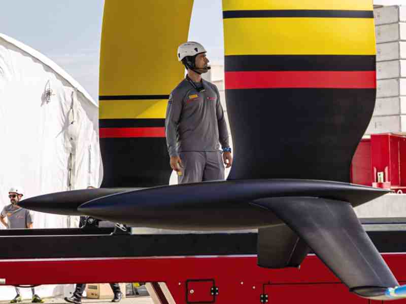
“The foil arm comes down to a junction, and at the bottom of it is the foot. And from there down is where teams have freedom in design; in our terminology, we call that the foil wing. The foil wings must be symmetric about centerline. They have articulating flaps like an airplane. There’s also a very stringent weight and center-of-gravity rule for the foil package. As you design the wings, you need to be very cognizant to meet that center of gravity and weight.”
There are also geometric limitations on the foils, explains Nick Holroyd, chief designer with INEOS Team UK. “If you’re looking from the transom forward [the rule defines] a trapezium-shaped box. While longitudinally the foils also have to fit [in the space] between 10 and 12 meters forward of the transom. You have this 3D box that the foil has to fit within. The trapezium is about 4 meters across its base, and to some degree, that defines the maximum span the foil can have.”
The final restrictions are on the numbers of these parts that the teams are allowed to build. “The foil wings, you’re allowed to build only six of them, three sets,” Jordan says. “Then there is a rule that once you declare them, you’re allowed to modify [as many times as you want] up to 20 percent of the mass. It actually gives you quite a bit of freedom for significant changes to them.”
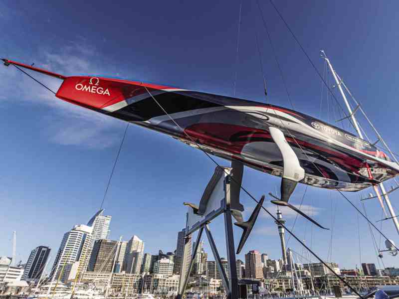
An Overview of the AC75
These restraints have led to teams making asymmetric sets of foils, so that within one pair, they can explore two different design avenues.
The whole T-shaped foil package is lifted in and out of the water by what’s called the foil-cant system, or FCS. “It’s another one-design part,” Jordan explains. “It’s a compulsory system that everybody has to use. It’s a big electrohydraulic system that does the cant of the foil arms. The [only] allowed movements of the foil arms are cant about a fore and aft axis. This system has a one-design battery to power it, so the power for canting the foils is not manpower.”
The teams use the same battery to control the foil wing flaps, even though this is a part that they can otherwise themselves design and build.
One-design parts have attracted their share of controversy in the past couple of years, and Jordan was deeply involved in the most serious of them. “The Challenger of Record Luna Rossa [Prada Pirelli] and the Defender [Emirates Team New Zealand] wrote the rule behind closed doors, and they divvied up responsibility for the one-design parts. Team New Zealand took on the responsibility of designing the foil-cant system, the hydraulic package. And Luna Rossa took on the design of the foil arms, the structural foil arm, which is a very critical part, as you can imagine.
“[Luna Rossa Prada Pirelli] pursued a method of construction that some of us have learned in the past doesn’t scale up to this size. The method of construction was basically a closed-mold composite structure. And there are a lot of foils built with that style of construction, like daggerboards for IMOCA 60s. But we tried to build boards that way for the big Alinghi cat [AC33 in 2010]—we actually built 14 of them. Most of them were not successful, because as you scale it up, the thickness of the composites gets so great that a lot of the thermal stresses and things like that just start to become gremlins.”
Despite the warnings, Luna Rossa Prada Pirelli’s engineering team went ahead.
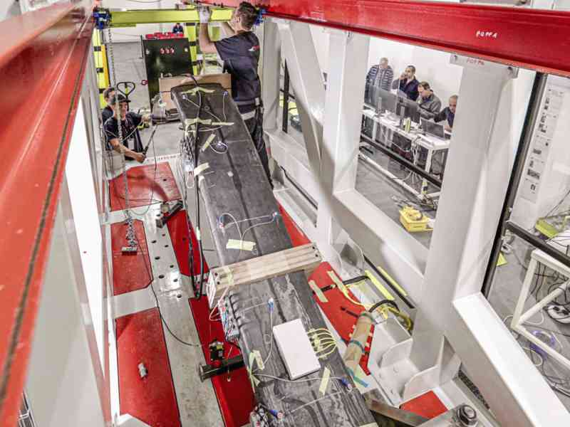
“They were pretty confident that they’d improved since what we learned in those days. So they built a test set, and a bunch of us went over to Persico for the first load test. It failed the load test, and at that stage they—kind of with open arms—embraced a consortium of engineers from all of the teams to create a working group who all collaborated on the design for what is now the foil arm. It was a painful start, and there were a lot of delays. We were delayed five months sailing our first boat because we didn’t have foils. It was controversial in that way, but they took on a very hard task.”
The new working group set to the problem and developed a new design that was also built by Persico. “The foil-arm construction is what we are calling ‘C-plate’ or carbon-plate-style construction, which consists of multiple long, contoured 20 mm plates stacked edgewise to create the structural backbone.” This version passed the structural tests and has now been sailing on the boats launched so far. “The confidence in them is super high at this stage,” Jordan says.
The final part of the jigsaw is the FCS, as Nick Holroyd explains: “The foil-cant system was designed by Team New Zealand, and it’s a good pointer for the future of the Cup. As of the 31st of August of this year, the final spec of the foil-cant system was issued, and any modifications or design improvements now need to be made unanimously.
“That’s forced the same group of four technical teams [who dealt with the foil-arm failure] to the table, and it’s been a very positive step because there are a number of technical issues still outstanding with the foil-cant system. It is prone to contamination within the hydraulic oil, and then that contamination undermines the reliability of the system. It’s in nobody’s interest—least of all the event’s—that there are races that are decided by the reliability of a supplied one-design system; that would be an awful outcome for the event.”
There isn’t much time left, with the opening races slated for Christmas, and the teams are all taking the problem seriously. “We’re only just a month past that [August] date, and we’re into having weekly meetings between all the teams, and there’s some really good work happening,” Holroyd says. “My takeaway from watching this Cup cycle is that we’ve produced far better results with all the stakeholders at the table.”
The various issues with the one-design parts have also proved a distraction from what should be the real work: designing the parts that the teams can control —the foil wings and their control systems or mechatronics.
“We are operating in a fluid that is 800 times denser than air, and so you end up with these foils that are quite small but—because of the fluid density and speeds you’re operating at—are capable of producing astronomical amounts of force,” Holroyd says. “If I’m designing a foil that will take off at 15 knots boatspeed, then it follows that it can produce enough lift for the boat and the crew; that’s seven and a half tons [of lift] at 15 knots. And I’m contemplating top speeds of, let’s say, 45 knots, so three times the speed. This means—because of the speed-squared term that occurs in all kinds of fluid dynamics—the maximum lift at 45 knots could be nine times the weight of the boat.”
And that would be nearly 77 tons of force being derived from those frail-looking flaps on the wings.
“The strength requirement—both for the structure of the wing itself, and the design and manufacture of flap-control systems [to fit] in such a very small space—to deal with those loads is quite tricky. The mechanical packaging side of these is a big deal.”
Jordan concurs: “You want an articulating flap that’s hydro or electric, or a combination system that controls the flap angle in salt water. And it deflects a lot. It’s just a huge mechanical-engineering challenge to cram the systems in there. And across the fleet, there have been systems that we’ve already seen where there are gears, cams, and tiny little hydraulic pushers and pullers. It’s unclear, I think, exactly what will prove the best system for these things over time. But a lot of clever mechanical engineering is going into it from all the teams because it’s a very tight package down there.”
One consequence of this is that some of that engineering is external on some of the wings, as Jordan points out. “If you have seen wings with a bunch of little strakes sticking down, for example, or sometimes up. Those, just like you see on an aircraft, those are for control systems for the flaps.”
There are two more aspects to the mechanical-engineering problem that the design teams face; the fluid dynamics and the rules on center of gravity and mass—all three of these things interplay. “It’s actually the packing of the ballast that really starts to drive a lot of the design trade-offs,” Holroyd says. “At one end of the design spectrum, you can have a larger wing area and package most, if not all, of your ballast within the wing section. Or if you want to go for a smaller wing area, then ultimately, at some point you have to sprout a bulb or a ballast package of some description to meet that weight/CG requirement.”
What are the advantages of small wings and a bulb, versus larger wings and no bulb? Larger wings will provide more space for engineering the flap articulation—but that’s just the start. Jordan says: “The foil that gets you up and foiling early—which is very important—and the foil that does good maneuvers is not the foil that gives you high speed. In very simple terms, a bigger foil helps you get out of the water sooner. But then at high speed, it’s a lot more drag. And so teams are trying to balance those two characteristics to find what’s optimal for getting around the racecourse.
“If you see a wing without a bulb, a visible bulb, for sure it’s going to be on the larger size because it has to pack the ballast into it. That’s going to be a wing that’s geared more toward early takeoff and maneuvers. And when you see a wing that has a center bulb, then that’s one that they’re going for the least amount of wetted surface, and it is leaning more toward top speeds. It’s the balance between those two goals that is kind of the holy grail…a bit of a challenge, for sure.”
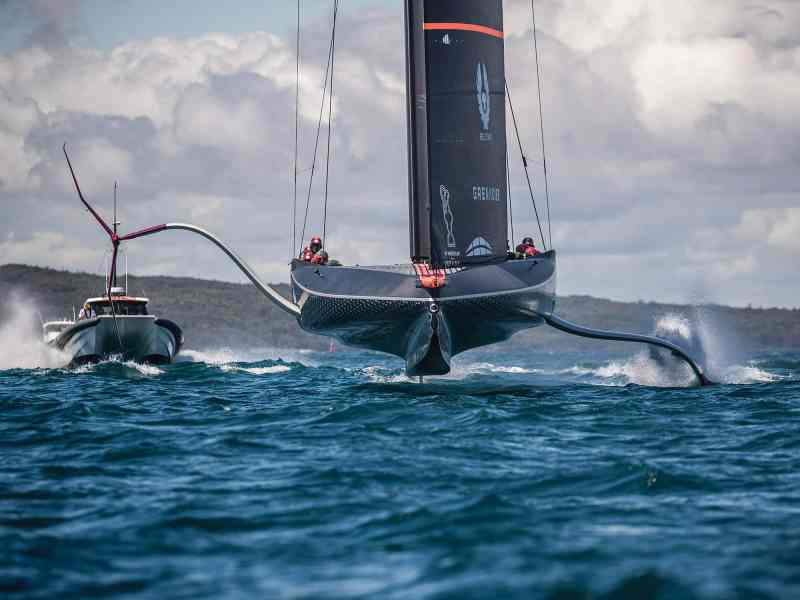
The transition to foiling was particularly important for Jordan. “Unlike the [AC] 50s, these boats seem to take longer to get up on the foil. So the team that can get back up on it in any kind of lighter conditions is going to have a huge advantage, because you can go from 10 knots to 30 knots with that transition. Even in the higher wind speeds, it’s a little bit cumbersome. A fundamental difference with these boats versus the boats of the last Cup is that a multihull has the majority of its righting moment when it’s sitting flat in the water. These boats have very little righting moment until they start to lean on the foils—and they start to fly. It makes the transition from displacement to flying harder than a multihull; it’s a balancing act between leaning on it and not tipping over.”
Wind speed will also be a factor in this calculus. Lighter wind will make it harder to get quick takeoffs and stay airborne during the tacks and jibes, while stronger wind means higher top speeds. The right balance in the trade-off between big foils versus small foils plus bulb will be very different at 8 knots of wind speed, and then at 20 knots of wind speed. This makes the designer’s job even more difficult, thanks to a change in the way this Cup regulates measurement certificates. In previous America’s Cups, the teams could change the certificate each day, and so they could change configuration according to the weather forecast.
“We have a single certificate that needs to be declared five days prior to the Cup and the Challenger Final,” Holroyd says. “This puts the racing outside the forecast horizon. It frames the design problem as creating an all-purpose set of foils, really based on the climatology statistics for the venue.”
He points out that a lot has changed since the Cup was last held in Auckland in 2003. The racecourses have moved into the harbor, and the race start time has changed from 1 p.m. to 4 p.m. “The expectation is that the average wind speeds will be a couple of knots higher than they were for the racing in 2000 to 2003,” he says.
We all know that the average wind speed is not the only wind speed that the boats will race in and that—while a truly all-purpose set of foils would perform at both the lowest speeds in light winds, and at the highest high speeds when it gets breezy—in the end, something has to give in the trade-off.
We shouldn’t wrap up without a word about the rudders. Unlike the T-foils, the rudders work in the same way as on the AC50 catamarans.
“We have two axes of rotation of the rudder, both centered on the bottom bearing,” Holroyd explains. “One is the vertical axis; it’s the conventional steering rotation of the rudder, and that must be connected to a steering wheel. The second axis is transversely across the boat through the bottom bearing, and that allows us to rake the rudder fore and aft, increasing or decreasing the angle of attack on the rudder horizontal element [often called the elevator], and that gives us pitch control of the boat. In both cases, we are trading control versus wetted area and outright speed.”
Put simply, the bigger the rudder, the more control the helmsman has but the slower the boat will go because of the extra drag. “The simulated environment is central for making those trades, and ultimately, it’s a decision that you really need to make with the pilot and helmsman.”
It should be clear by now that while the design problem has undoubtedly got more dimensions in a foiling boat, its essence has not changed since Capt. Nathanael Herreshoff drew Reliance. One thing must be traded for another—ease of takeoff against top-end speed, steering control against straight-line speed, and so on. The designer’s job is to pick the right balance, and then optimize that solution to within a micrometer of its life. For all the froth and fuss over foiling, this balancing act will be the essence of this America’s Cup…just like all the others, before and after.